Automate Schematic Symbol Libraries
How much time does your team spend creating library Symbols for Allegro®, Altium®, EAGLE™, Mentor®, OrCAD®, or Zuken® Schematic tools?
Take a Look at PartBuilder.
PartBuilder automates the creation of symbol libraries for your current EDA tools, saving you precious time, and eliminating costly errors.
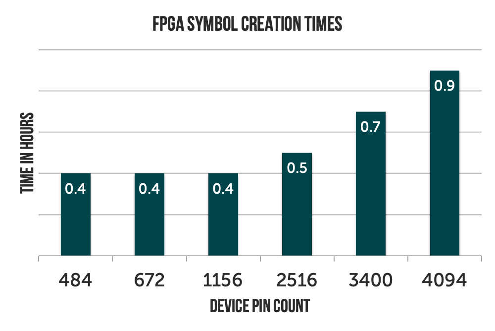
Build parts with 25-100 pins in 15 minutes, 200-1000 pin parts in a half hour, and any size FPGA from Xilinx, Altera, Lattice or Microsemi in less than an hour.
Click on video to the right for a brief introduction to the power of PartBuilder.
Accurate and Efficient
PartBuilder creates logic symbols for devices and easily scales to handle parts with 10 to 10,000+ pins. The creation of smaller graphical parts is not currently supported by the tool.
Pin-Extract, Smart-FRAC and the Symbol Description Language (SDL) enable the computer to do the majority of the work to build your symbols.
Create symbols for any Intel/Altera, MicroSemi, Lattice, and Xilinx FPGA from 100-4000+ pins in under an hour.
Create symbols for processors, switches, ASICs, and other devices in under an hour per thousand pins.
Work Smarter, Not Harder
Ultra-fast Pin Data Extraction
Pin-Extract extracts pin data from over 20 industry sources, including BSDL, IBIS, FPGA vendor files, and even existing library symbols. PDF Datasheets with a wide variety of Table or Pin-Map formats can be converted into Spreadsheets using free online tools or affordable tools available from vendors like AABBY and InvestinTech. Our Zero-Touch Adaptive SpreadSheet technology minimizes user editing required for pinReports to avoid errors that can occur due to use modifications.
Pin-Extract performs extensive error checking and reporting on the input data, and has been known to identify real errors in vendors released datasheets
The PinExplorer operates on the extracted pin data and enabling the user to interactively modify pin types and quickly group sets of related pins without touching the vendors source data.
Smart-FRAC creates the Symbol Description Language (SDL) for your component. It intelligently sorts the PinData from Pin-Extract to build efficiently packed groups of busses, diff-pairs and Power pins. It automatically distributes all the device power pins, across the minimum number of symbols needed, The initial SDL file created by Smart-FRAC places every device pin in a very functional set of symbols for any size device. It is then up to the user to perfect the output for their application.
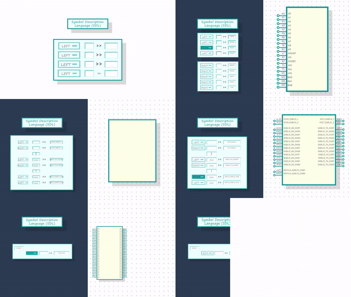
The Symbol Description Language (SDL)
The Symbol Description Language is a small text file or collection of text files that provides simple instructions to tell your computer how it should build your symbols. In most cases the initial Symbol Description Language file is created by Smart-FRAC
Simplifies fractured symbol construction
Place hundreds of power pins across multiple symbols with one statement.
Place 32-bit wide bus of diff-pairs with another.
Easily add Visible Pin Bubbles and Clock Modifiers
Define groups of swappable pins using Pin-Swap Modifiers
Simple Loop constructs let you replicate similar symbols and/or similar interfaces within symbols
Include Files enable maximal reuse of symbols you’ve already created.
The IS_PIN modifier is used to create huge connectors and TQFP type devices using the physical order of the pins in minutes.
.
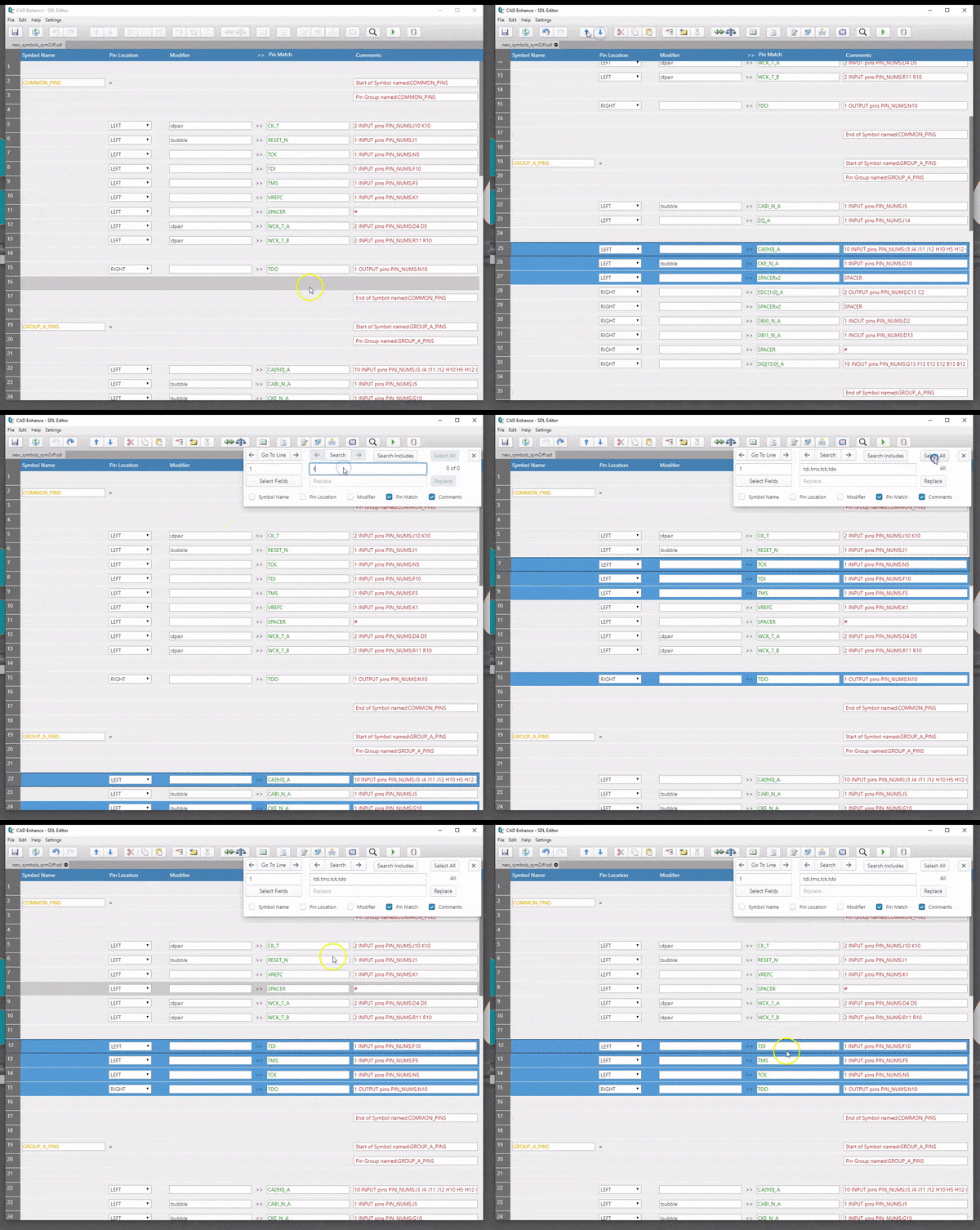
The SDL-Editor
With PartBuilder the majority of time in the symbol creation process involves re-ordering and perfecting the SDL created by Smart-FRAC to describe the exact set of symbols your customer wants.
While the SDL file is just a text file and can be editied in your favorite text-editor, we built the SDL-Editor from the ground up to provide the optimal tool for our users to re-order the SDL pin placements with efficient spacing commands. Our editor is a hybrid of a spreadsheet program and a text editor with powerful search and replace options specific to SDL and symbol definition.
Operations like move, cut, paste and squeeze work on selected groups of rows which do not need to be adjacent.
Buttons and context menus enable Insertion of Pin-matches, Spacers, Start and End of Symbols commands
Provides advanced support for Loop Insertion and for creating/inserting and replacing Include files.
Search and replace can be constrained to work on pin-matches, comments, modifiers, and symbol definitions, and can also operate on multiple levels of include files.
The user can enter multiple search strings for pin-matches in the order they would like pins to appear within a symbol, The editor will find the pin-matches and re-order them for the user as a result of the cut-and-paste operation
Special leveraging operations allow users to move and substitute groups of pin-matches and spacers without moving other sets of pins
Create FPGA Symbols 50x Faster
PartBuilder can easily create symbols for any size FPGA from Xilinx, Intel/Altera, Lattice, and MicroChip/Microsemi in less than an hour. How is this possible?
Pin-Extract provides support to read all of the vendor Pin report formats. It takes mere seconds to extract the device pin data including bank location and order in the bank, and even pin-delays from the proprietary vendof files.
Smart-FRAC understands the repetitive banking structures of each vendors device and quickly build an SDL file describing a symbol for each Generic I/O Bank, and each HighSpeed transceiver bank. It separates the dedicated configuration pins into their own symbol and then distributes the remaining power pins using a carefully designed algorithm to fit into the fewest symbols needed.
In fact, the first pass SDL output created by Smart-FRAC creates a very functional set of symbols for the selected device in under 5 minutes… even for a giant 3824 pin device!
The rest of the work involves editing the SDL to reduce symbol counts by combining sets of banks into one symbol. This is where SDL-loops come in very handy. The user can also fine-tune the locations of the configuration pins and power pins if necessary. The use of SDL-Include files is very helpful here to create consistent symbols for devices in the same FGPA family/
generate parts simply
Select the type of pin data and provide the pin data for extraction
Create rules to rename pins and redefine pin types, if needed
Run Smart-Frac to create initial SDL
Edit SDL to arrange pins around a limitless number of named symbols
Define and edit part property placement and content
Generate the symbols for any enabled EDA tool following your library standards
Release the locally created symbols to your library when the part is ready
Refine and update symbols at the touch of a button.
Verify And Compare Your Existing Symbols
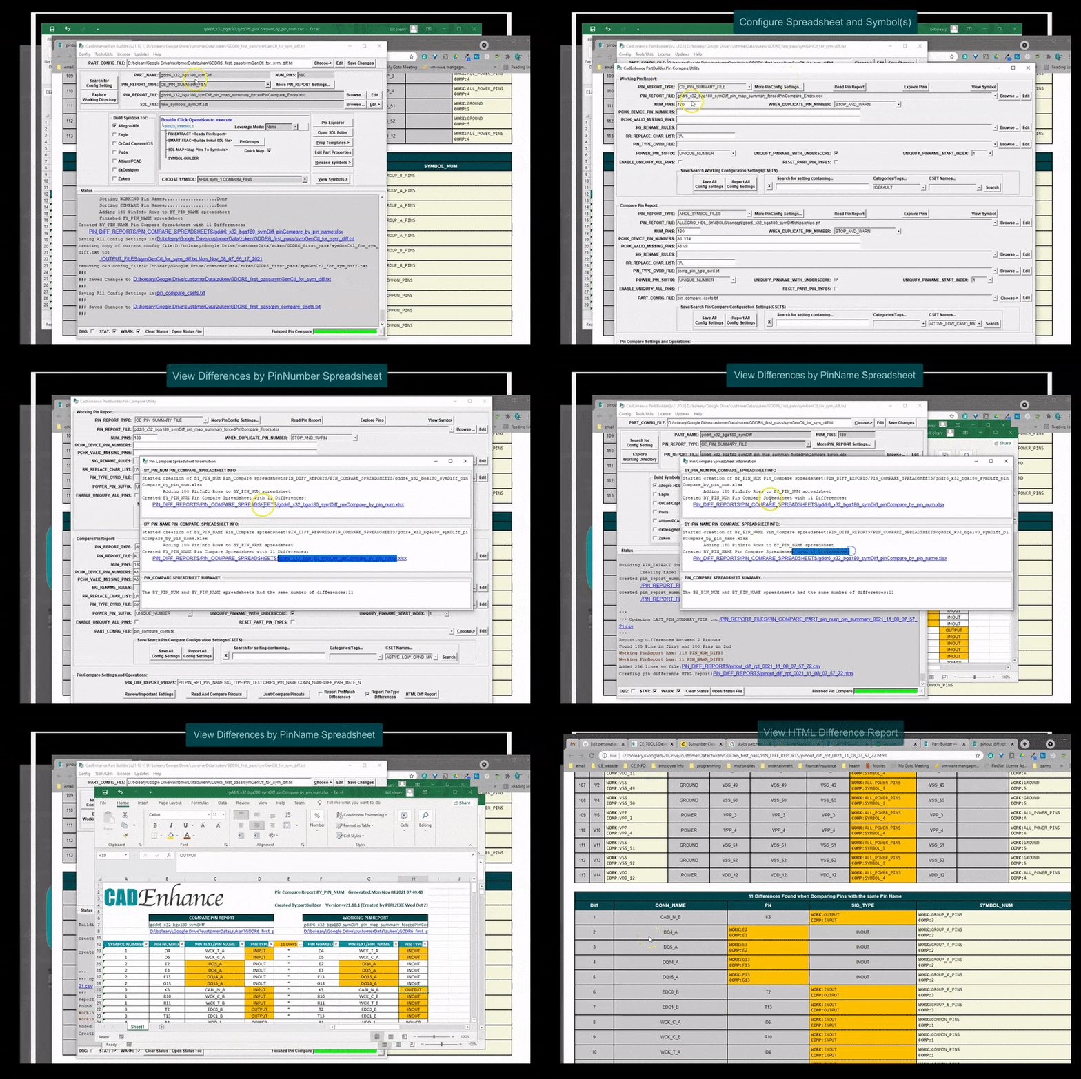
PIN-COMPARE Reads an existing symbol and compares it to any pinReport format supported by Pin-Extract (including another symbol file)
It produces detailed spreadsheets and HTML reports highlighting differences in PinNumbers, Pin Names or Pin Types
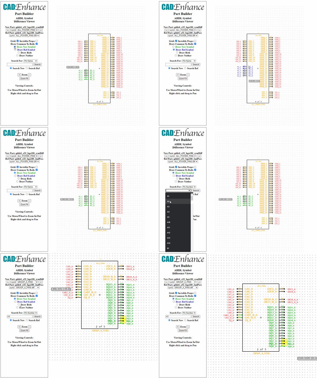
Graphical Symbol Compare Reads two sets of symbols to creates a fully featured HTML viewer which overlays the symbols on top of each other using different colors to highlight the differences.
Compare Revisions of the same symbol or 2 completely different symbols
Translate Existing Symbols to Your Tool
Translate existing AllegroHDL, Orcad, or dxDesigner symbols to all supported EDA tools following your library standards.
Part Templates
Use your existing symbols to establish a set of rules to build symbols to your standards. A set of site rules can be maintained to define your company’s symbol standards, ensuring every part is built following your guidelines.


